Task performance↑ Maximize
Jump height
m
Predicted vertical slider rise, capturing how the actuator and joint control perform together.
AN INTERACTIVE RESEARCH COMPANION
A stronger actuator doesn’t always make a better robot.
Build the hardware. Shape the control.
Discover what happens when you design them together.
An independent teaching model; results do not reproduce the paper’s actuator predictions or experiments. Inspect these formulas ↗
Diameter ranges reserve room for slots and the stator yoke.
One design, used at both joints.
48 V equivalent supply · 5.5 kg payload.
Ideal gearbox · no transmission loss.
The force vector must stay inside |T| ≤ μN.
How should the joints share the push?
Drag either curve’s points to edit its effort.
The hip and knee can move independently when the foot slides. A poorly coordinated push can kick the foot out instead of lifting the body.
HARDWARE × CONTROL
Compare your starting design with control optimization, hardware optimization, and co-design.
A bounded numerical search, not a guarantee of a global optimum.
This is an educational model for exploring trade-offs. Its numerical results are not predictions for the fabricated actuator or a reproduction of the paper’s validated simulation.
Slot area and air-gap geometry set nominal torque under fixed electromagnetic loading assumptions. A DC-equivalent circuit applies separate current and voltage limits. Iron and copper volumes contribute to mass; the gearbox is ideal. Reference constants are illustrative and uncalibrated.
Read every equation, assumption and source ↗The 0.25 m thigh and shank have independent joint motion while the foot slides. Hip motion stays on a vertical guide. Static friction may hold the foot; at its limit the model switches to sliding and keeps integrating both joint coordinates. Six Bézier coefficients per joint set effort over knee extension.
Sliding: T = −μN sign(vfoot)Sliding dissipates energy but is not an automatic failure or score penalty. The site reports actual body rise and foot travel. Upward takeoff uses COM velocity and a frozen-pose flight approximation. Ground collision, joint travel limits, or unloading without upward COM velocity end an unsuccessful attempt; flight joint dynamics and impacts are not integrated.
Inspect the contact model ↗TASK-ORIENTED ACTUATOR CO-DESIGN
The research couples motor electromagnetic design, planetary gearbox sizing, actuator mass and inertia, and task dynamics. Surrogate models make the hardware search tractable; joint torque policies are optimized for each candidate.
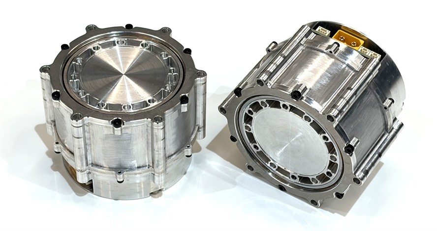 Fabricated actuator
INSIDE THE PAPER
From electromagnetic geometry to gears and task feasibility, each candidate must work as a complete actuator.
Fundamental winding factor kw,1 > 0.9.
Valid stator and slot geometry.
Positive clearances and manufacturable geometry.
Realizable winding and current / voltage limits.
Assembly and ratio feasibility.
Gear geometry and tooth-root strength constraints. Member-level boxes illustrate 3K; NGW and NW use different member sets. Repeated physical planets share the same member design. These counts are parameter entries, not unconstrained degrees of freedom.
Each coefficient ranges from 0 to 1. Separate curves determine how the two joints share the push.
Derived quantities and constraints
OPTIMIZATION TARGETS
Predicted vertical slider rise, capturing how the actuator and joint control perform together.
Rated output torque per unit actuator mass, evaluated at a common conductor current density of 6 A/mm².
NSGA-II searches for Pareto-optimal trade-offs between these two objectives.
PAPER RESULTS
Higher torque density does not always mean a higher jump.
Select a group to highlight it. Hover or tap a point to inspect its objectives.
All slot–pole combinations
The fabricated actuator alongside the DM8009 reference.
48 V · 5.5 kg bench load · twice-rated torque: 40 N·m / 52 N·m. Rise includes extension from the initial crouch.
Nominal rated output torque divided by actuator mass. Prototype: 26 N·m / 0.729 kg.
Measured prototype mass compared with the DM8009 reference mass.
The fabricated prototype was selected from an earlier design search. It is not a newly fabricated point from the updated dual-joint Bézier co-design Pareto set.